Leica Tile Scans- a brief overview
Leica tile scans- the basics
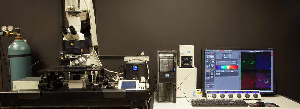
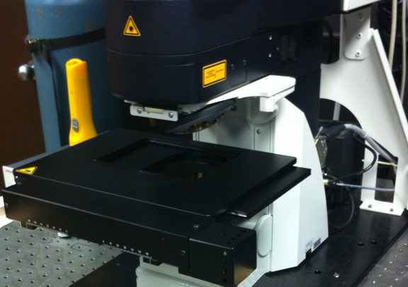
To do a tile scan, the scanning stage needs to be installed. If it isn’t, you will need to contact the core manager and arrange a stage swap. This is what the scanning stage looks like:
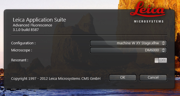
Before you begin the start up process, make sure the stage insert is removed and the 10x objective is in the home position (i.e., over the condenser). When you start the LAS software, select “machine W XY Stage.xlhw” in the Configuration option.
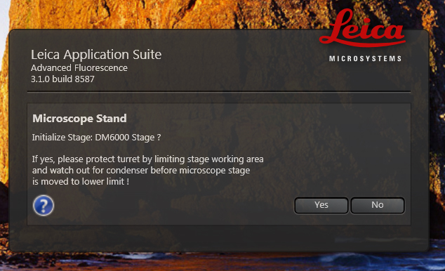
The program will then ask (a few minutes later) whether you wish to initialize the stage. Click “yes”.
Once the LAS software has started, go to the “Configuration” Tab and select “Stage Configuration”.
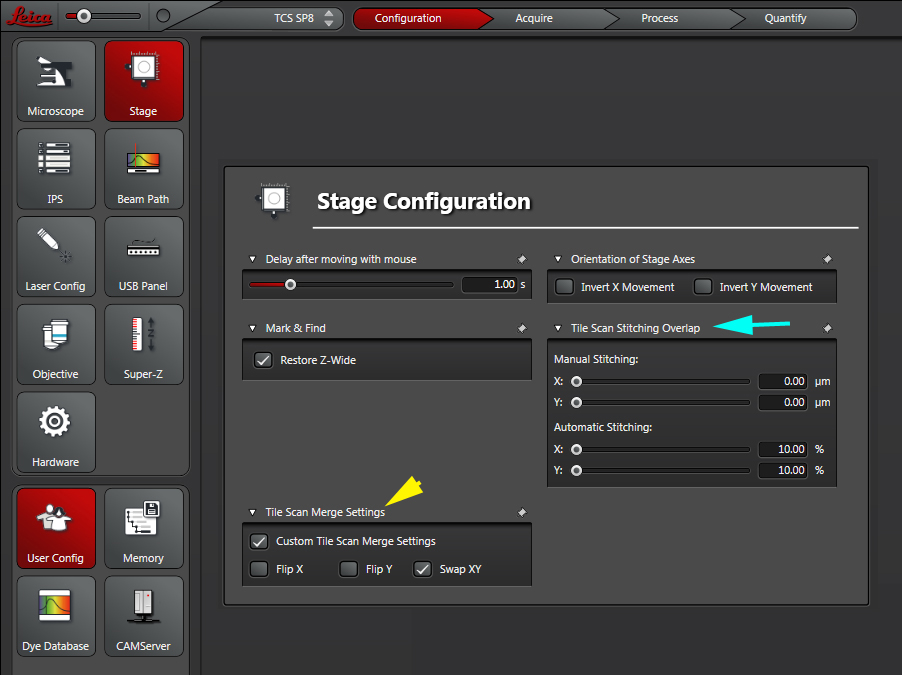
Check the “Tile Scan Merge Settings” (yellow arrow). Make sure “Swap XY” is checked. You can opt for automatic stitching (10% is default, but you can change it) or manual stitching (blue arrow).
Turn on the lasers, go to the “Acquire” Tab, and click the “Define Overview Image” button:
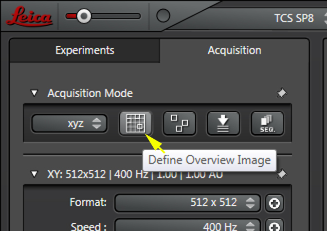
This opens a Tile Scan panel below:
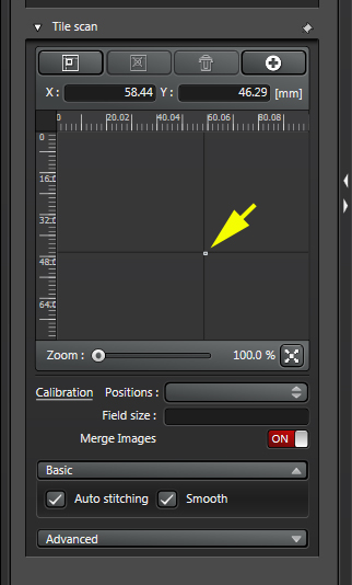
The current field of view is represented by a rectangle of the grid (yellow arrow). You can use the Zoom bar to enlarge it:
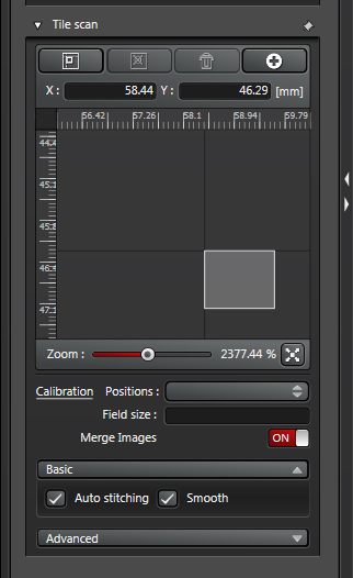
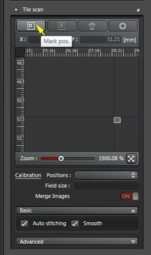
You set your matrix by assigning the cross-corners of the square/rectangular region you plan to image. Clicking the “Mark Position” makes your current FOV the first corner.
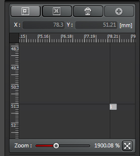
You will now see a “1” in the location square:
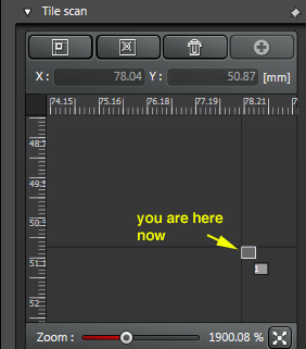
To move to another place on the grid, you can double click a spot on the display, or move the FOV via the x/y control knobs.
Clicking “Mark Position” again will set up a matrix around the corners you’ve picked (you’ll see a “2” in the latest region clicked):
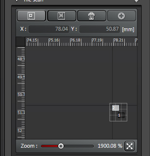
IF you decide you want a bigger area scanned, you can move the FOV and click on a third point. This will replace the last point selected (the 2nd point) in defining the matrix.
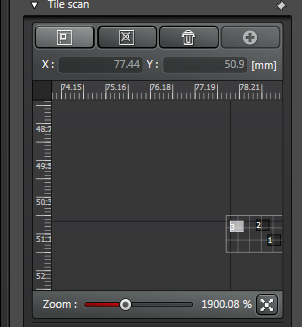
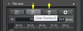
Clicking the “Clear Position“ button will erase the last position selected. You can also click the trash can icon to erase all the selected positions.
You can also set Z stack limits, setup/load a sequential scan protocol, etc. in addition to setting the matrix.
