Know your Leica controls, The Acquisition Panel, part III- the right
The right side of the acquisition panel gives you the image display(s), and various controls for adjusting them. This section will first describe the buttons most commonly used to manipulate the displays, and then provide a summary of all the buttons and their functions.
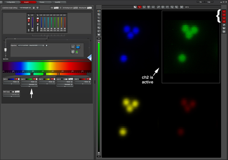
The right window will show an image for each detection window that is on. In the example below there are 4 channels. There are numbered buttons at the top right that control the display of each channel (indicated with the white bracket). When a button is red, the channel display in on. Clicking a button turns it grey and the image for that channel is removed from the screen. A second click reactivates it and restores the image.
The box around channel 2 indicates that it is active; that means the saturation levels can be adjusted with the USB controls. To activate a different channel, left click on its image.
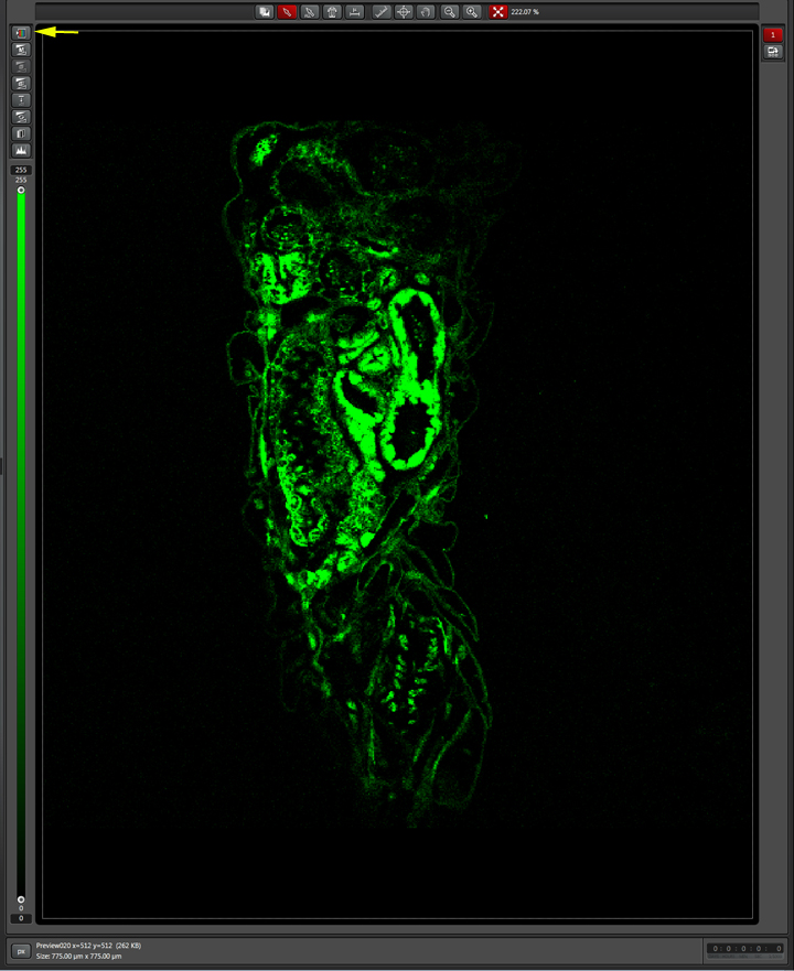
The “QuickLUT” button (LUT = Look up table) is located at the top left of the panel (yellow arrow). It has 3 different settings, which you can click through. LUT setting1 shows the image in the selected color:
If you wish to change the color, left click the color bar on the detector window, which opens a new window:
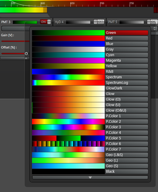
Double left click on the text of the new color to make the change:

LUT setting2 gives you the high-low mode, which is used for setting the pixel saturation limits:
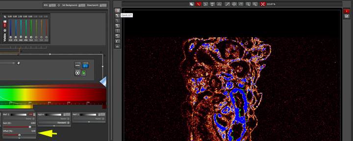
In the Leica system the zero pixel (no photos) is represented in green. At the opposite end, the saturated pixel (255 with 8 bit) appears blue. The saturation spectrum runs from green to black to red to cream to white to blue. The gain controls the saturation (high gain = more saturated pixels). Ideally, you would like to see a few blue pixels, representing the brightest portions of your image. Offset is used to “set the floor” or define the zero pixel. Adjusting offset to the left (negative values) “raises the floor”, and more green will be seen in the image.
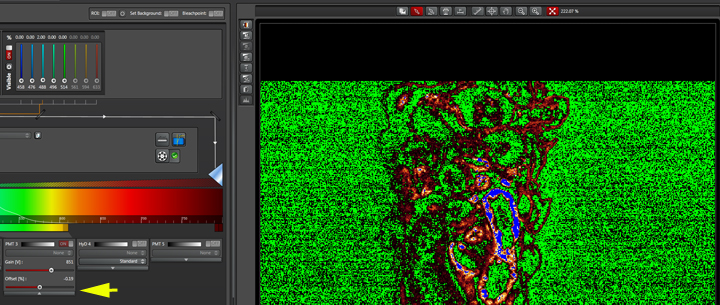
The ideal offset setting is a judgment call. More green (a higher floor), will clean up the background, but there is the risk of losing fine detail.
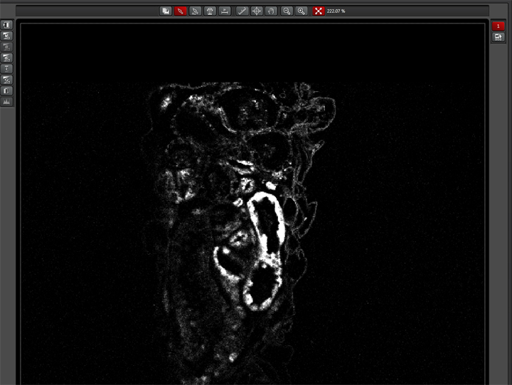
The 3rd LUT setting gives you a gray scale image:
The top left buttons
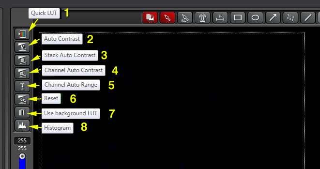
The Quick LUT button (1) is described above. Buttons 2-5 are scaling mode buttons that allow the user to adjust the grey scale value range, represented by the slider (in blue) below these buttons. In this example the color depth is 8 bit, with a range of 0 to 255. Button 2 toggles between “Auto Contrast” and “Manual Contrast”. Button 6 will revert the images to their original contrast settings.
The top center buttons
These buttons control the tools used to annotate the images. They allow you to do things such as draw/delete regions of interest (ROIs), and add text, arrows, scale bars, etc. Clicking the leftmost button will give you the full menu of annotation tools.
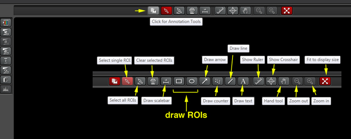
The right side buttons
The tools on the right give you display options for your images. They can be confusing at first in that they can disappear and then reappear, depending on other buttons you select or deselect, or what type of scan you did.

The movie control buttons will be visible if you have a z stack active, and “Maximum Projection” is off. The channel buttons are described above; their number is determined by the number of channels used in the scan. “Maximum Projection” will produce a combined stack (be it z or t or λ) of all the active channel windows (including an overlay). “Show overlay” will add an image that merges all selected channels. “Orthogonal sectioning” produces virtual slices (x-z and y-z) through the stack (all active channels combined) in the lines defined by the crosshairs (which can be moved to any part of the image via left click and drag).
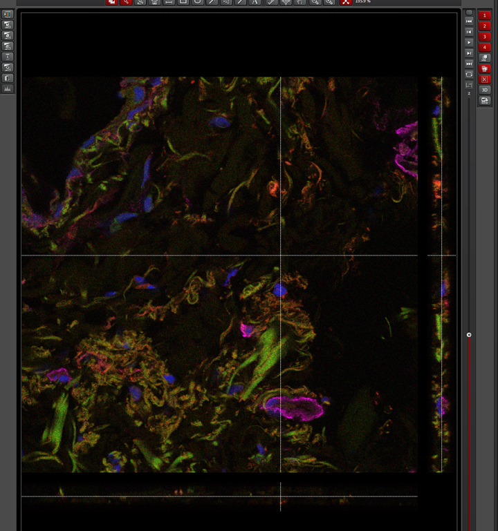
“3D” opens a new window for 3D manipulations of the images. “Show gallery” will allow you to scroll through all the individual images of your stack at the bottom of the window.
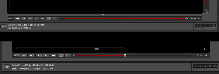
If you have a λ or t stack, the movie controls will appear under the image window.
