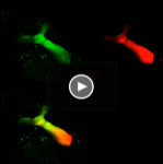
Doing Photo-conversion on the Olympus FV3000-Part I
One of the most useful tools for studying cell processes in real time are photoactivatable, photoconvertible, and photoswitchable variants of fluorescent proteins, which can experience a change in their fluorescent properties upon exposure to a certain wavelength of light. Photoactivatable proteins exhibit little to no fluorescence until exposed to a brief pulse of the light of the activating wavelength. This activation tends to be permanent, A photoconvertible protein is initially fluorescent, but will shift its emission spectra after photo-activation. Photoswitchable proteins can be changed multiple times between the active and inactive states. With expression of the appropriate photoconvertible proteins in the regions of interest of your live specimens, many dynamic processes, such as protein turnover, vesicle trafficking, cytoskeletal changes, and much more, can be investigated.
The FV3000 has a useful software option, Sequence Manager, that enables you to perform complex photo-conversion experiments in a single imaging run.
Some recommendations before you begin
1) Once you start up the Acquisition software, you will probably need to open two additional windows: “Sequence Manager” and “LSM Stimulation”. Use the “Tool Window” drop down menu.
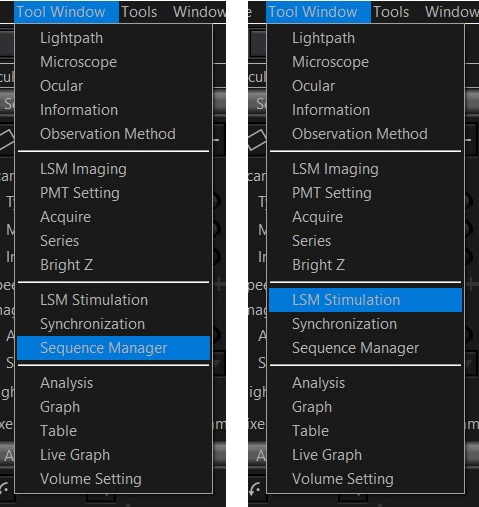
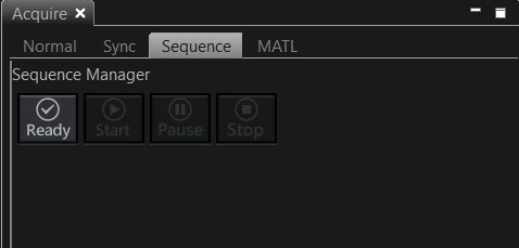
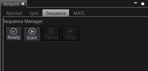
The Sequence Manager window should appear below the image window. The LSM Stimulation window will be tabbed with the LSM imaging window. Select the “Sequence” option in the Acquire Tab:
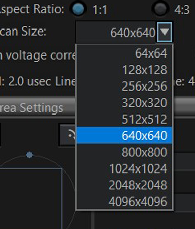
2) When performing any photo-stimulation experiments, optimizing pixel size is recommended. This will minimize any “leakage” of the photo-stimulating laser outside the area of the selected ROI(s). This optimal size (via Nyquist calculation) is indicated by the red arrow on the Zoom control in the “Area Settings” window. Clicking the “Optimize” button will zoom the image to recommended setting.
![]()
The position of the red arrow is influenced by the choice of objective and the digital resolution (Scan size) selected. If you don’t want to zoom in as much as the arrow indicates, increase the number of pixels in the field of view.
3) Be prepared to practice on extra specimens before you do the actual experiment. The ideal settings for photo-conversion or photobleaching for cells in culture will be different from the fly brains explants used in these examples, which will be different from cells/tissues in a zebrafish embryos, which will be different from other living tissue. Your goal is to determine the minimum amount of laser exposure that will accomplish your experimental objective.
The amount of laser power that hits an ROI on your specimen can be adjusted by three different controls: 1) The scanning speed of the stimulus laser. The slower the speed, the longer the pixel dwell time, and the greater the amount of light that is absorbed. 2). The selected intensity of the laser. 3) The number of times (controlled by Loop # in the Sequence Manager) an ROI is scanned by the stimulus laser.
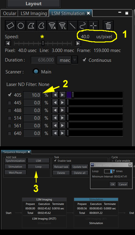
When determining the right conditions for photo-conversion or photobleaching, the laser exposure should be increased via these 3 parameters until the desired effect is observed. Then you should incrementally decrease laser exposure on subsequent specimens to determine the minimal exposure that gives you your desired photo-conversion or photobleaching.
Example 1: Photo-conversion of the Kaede GFP-variant in Drosophila brain explants
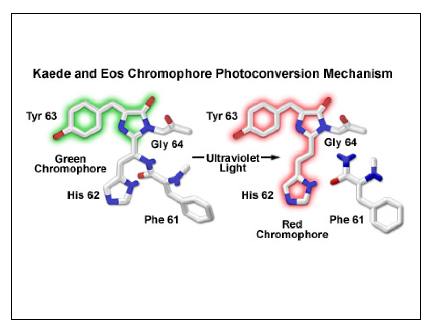
Kaede is a photo-switchable form of the green fluorescent protein. Absorption of an ultraviolet photon can break a covalent bond at Phe 61, causing a permanent structural change and a shift in the molecule’s emission spectra from green to red.
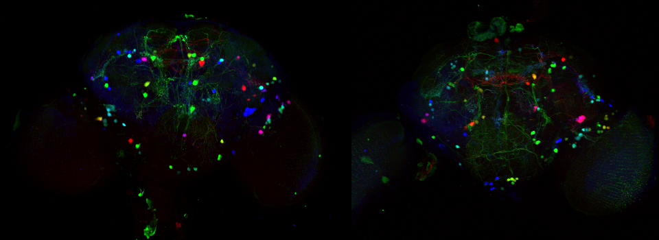
In this example, Kaede is expressed in the mushroom bodies of the adult Drosophila brain via an eyeless-GAL4 promotor. The Kaede protein is free to diffuse through the cytoplasm of the nerve cells.
Detector setup:
The FV3000 software has pre-set detector settings for Kaede. Open the Dye window and select both the green and red Kaede options.
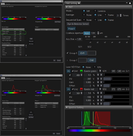
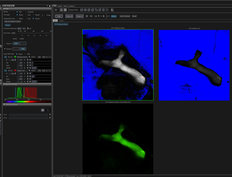
Scan your specimen with each laser (488 and 561 nm). The green signal should be strong and setting the detectors straightforward. The trickiest part is the initial setting of the detector for the red Kaede form. There is often a low background level of the red form (as you likely can’t prevent minimal exposure to UV light). If the 561 nm laser %/ channel HV is set too low, you may not record a photoconversion event, even though it did happen. If you see no change in the red channel after your first photoconversion attempt, Live Scan the specimen with a higher % for the 561 laser and /or increase the voltage on the red channel detector to see if the red signal actually did increase before trying photoconversion again with an increase in laser exposure. Once you determine the right detector settings, they will be stored as metadata in the next image you record and can be applied to all future photoconversion work.
Setting up the photo-conversion sequence:
For most photo-stimulation experiments, the basic design is to record an initial image, apply the photo-stimulus on an ROI(s), and then perform post-stimulus imaging, which may include multiple time points. With the Sequence Manager software, it is possible to perform separate photo-stimulus events with different lasers, pause recording, and repeat (loop) selected events.
Here is the Sequence Manager control bar:

For most applications you will want to check “append each task in each cycle as T series data” in the “Append” panel to the right.
There is a choice of five different tasks (Synchronization, Stimulation, Wait/Pause, LSM (laser scanning microscopy) and Loop) in the “Add Task” section to the left of the window. Set up the scanning parameters for your initial image, including any Z or T series settings, then click “LSM”.
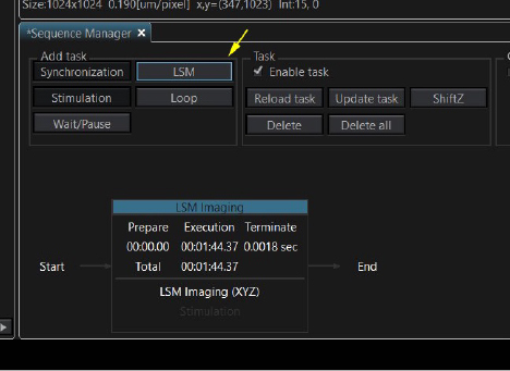
This is how it looks in the taskbar diagram. The initial image is a Z-stack of 16, taking 1 minute 44 seconds to collect.
The next step is a stimulation task, but it cannot be added until a stimulus ROI has been drawn on the preview image. Go to the “LSM Stimulation” tab:
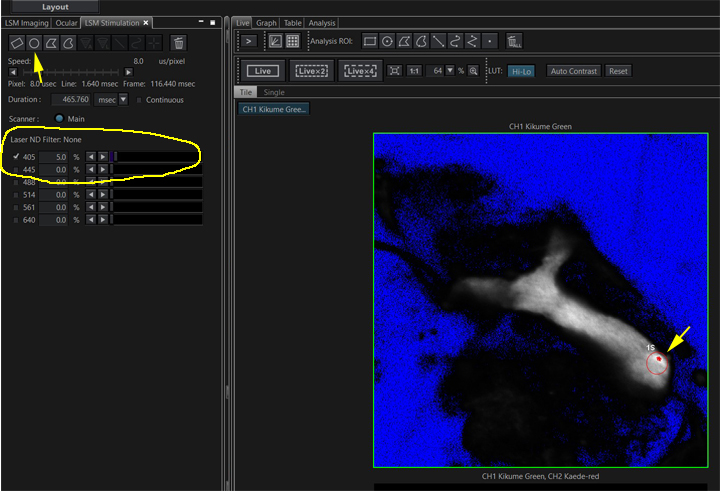
Use one of the ROI buttons to draw an stimulus ROI on your preview image (yellow arrows). Check the box for the 405 laser. The optimal setting for laser power will initially have to be determined through trial and error. For photoconversion it usually does not need to be set very high; in this example 5% will be used. The ideal laser speed must also be determined through trial and error; here the dwell time is set to 8 us/pixel. Now you can add the stimulation task to your photoconversion sequence:
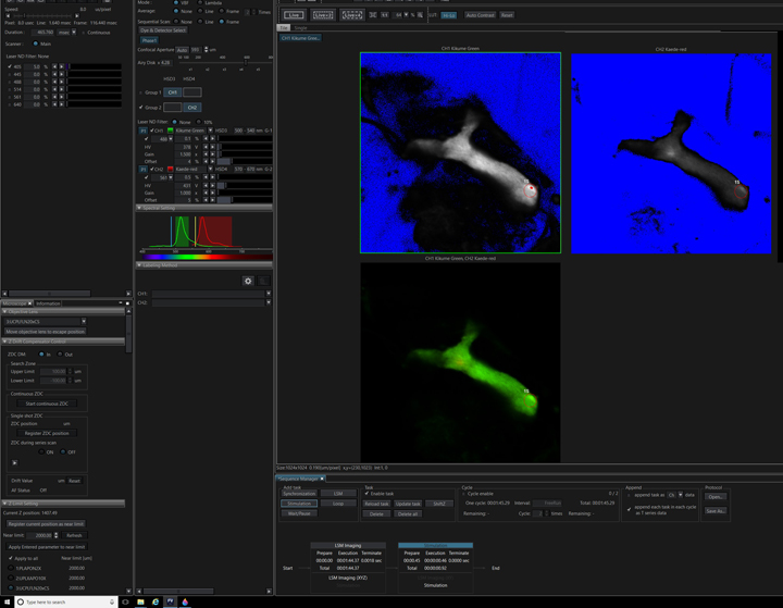
That final step is a post-photo-conversion imaging task. In this example a time dimension (ten iterations) has been added to record the diffusion of the converted Kaede red form through the mushroom body.
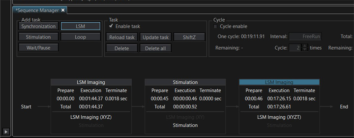
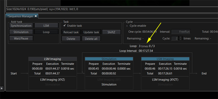
Once all your tasks are created, you have the option to loop one or more of them if you wish to repeat any steps. In this example, the stimulation and post-stimulation time lapse imaging will be done a total of 3 times. Select the task to be looped by clicking on it (the header will turn blue). If you wish to loop multiple tasks, hold down the CTRL key and click on the tasks. Once all the tasks are highlighted, click the “Loop” button, then select the number of times you wish to run the looped tasks (3).
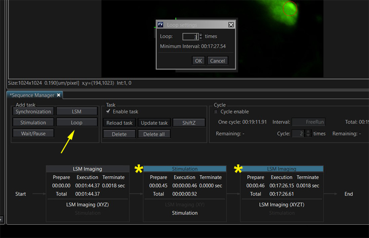
The taskbar diagram is updated to reflect this change:
If you want to make any changes to a task after you have created it (such as changing detector settings, laser power, or the number of steps in a Z or T series), you will need to use “Update Task” to insure the changes are registered.
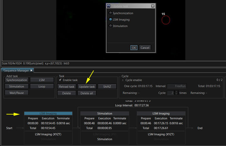
Select the task to update, click “Update task”, make sure that the right type of task is selected in the new window, then click OK. It’s a good idea to double check scan parameters and update all the tasks before running the sequence to be sure they are set correctly.
When you are ready to run the photoconversion sequence, click the “ready” button on the Acquire tab.
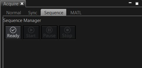
The software will check your instructions, and if they don’t conflict with the limits of the software, the “start” button with be activated.
Here is the image window after completion of the photo-conversion sequence:
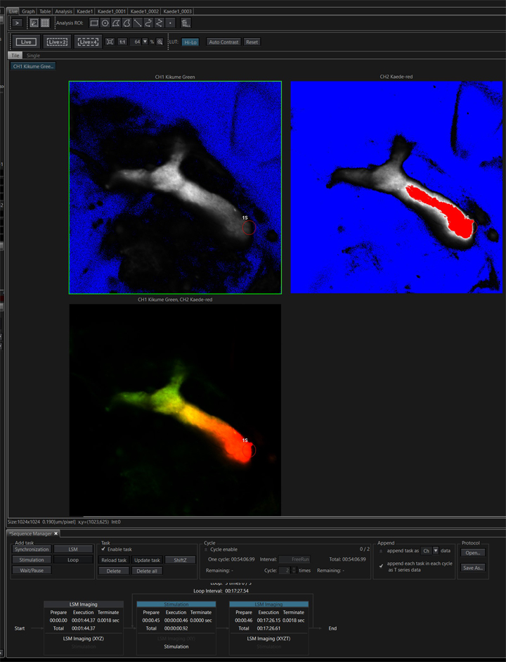
This run produced 4 separate image tabs:

“Kaede1” is the pre-photo-conversion image recorded in the first task. The next 3 (“Kaede1_0001, etc.) are from the 3 looped post-stimulation time lapse runs. The actuation photo-stimulation steps are not recorded. These files can be combined into a single image file with the “Viewer” program.
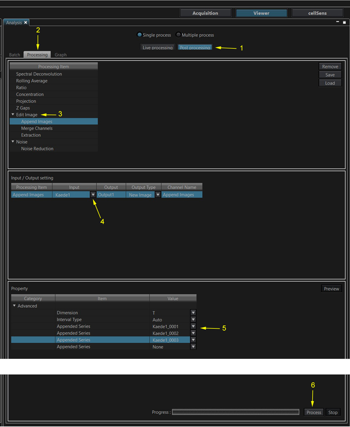
Select “Post Processing” (1), “Processing” (2), and “Append Images” from the “Edit Image” menu option (3). In the “Input/ Output setting” section use the drop down menu under “Input” (4) to select the file the begins the time series, in this case “Kaede1”. In the “Property” section use the “Appended Series” pulldowns to add the other files in the desired temporal order (5). Click the “Process” button at the bottom right (6) to create the appended file.

The new file is named “Kaede1_0004” and has 31 time points.
To make a movie file of the time lapse image, right click on the image window and select “Save Animation”.
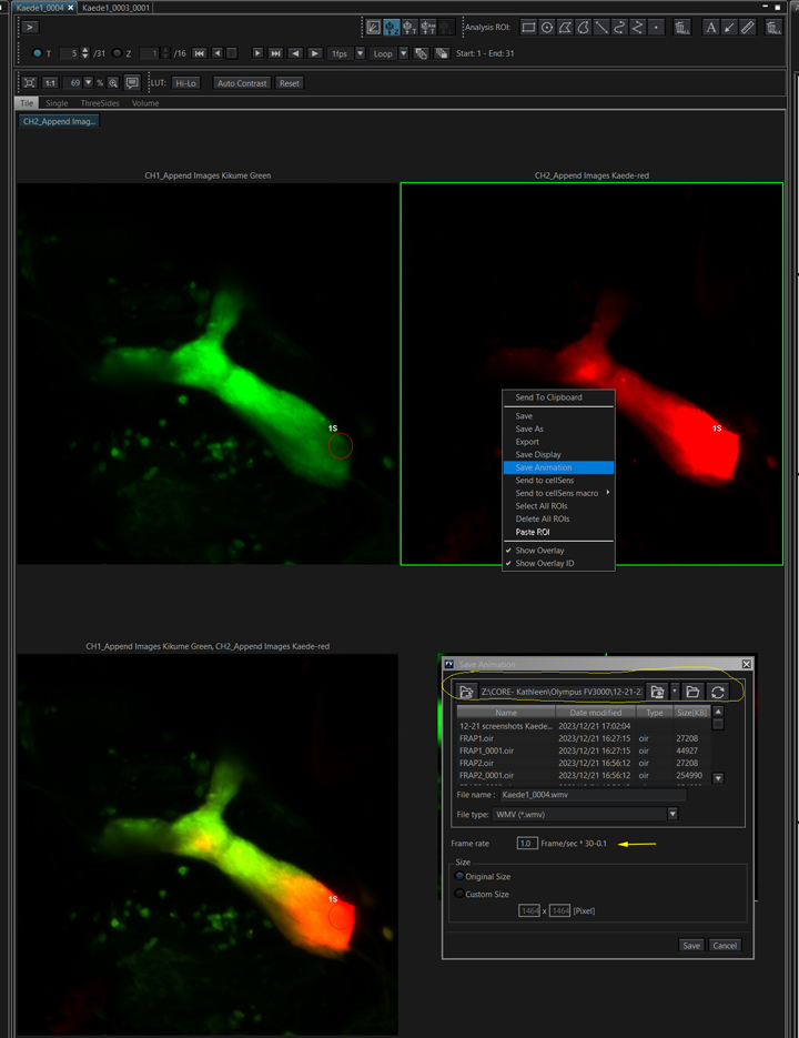
Check the file destination, as it may not be the same place you’ve been saving the data files. You also will probably need to experiment with different Frame/sec settings to find the ideal movie speed. The only movie format option is wmv.
