Using the Tokai Hit Stagetop Incubator
IMPORTANT NOTE: IF YOU ARE WORKING WITH BSL2 MATERIAL, YOU MUST ASSEMBLE THE INCUBATOR INSIDE THE BIOSAFETY CABINET
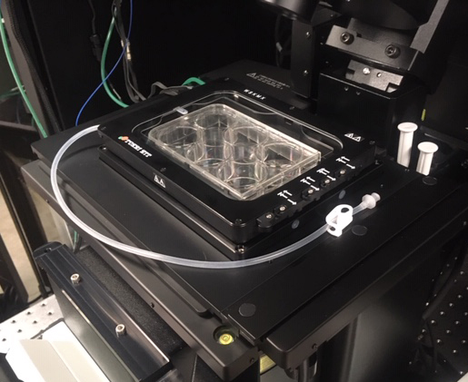
This device will allow you to maintain cells in culture under ideal conditions (temperature, CO2 and/or O2 concentrations, humidity) on the stage top as you do time lapse imaging. You may also use it without the gas for temperature sensitive small organisms such as zebra fish or frog embryos.
The chamber will take at least 30 minutes to warm up, so account for this time when you are making reservations. You will need to block off time for BOTH the FV3000 and the incubator on the Booked calendar.
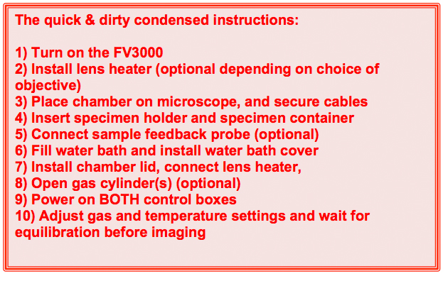
Shutdown is the reverse of above followed by cleaning all wet surfaces with alcohol.
The Tokai Hit Incubator System and its many parts
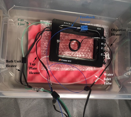
A description of all the lines and wires attached to the incubator:
1) The green tubing is the gas line, which delivers CO2 and/or N2 (for displacing O2) into the chamber.
2) The blue wire connects to the feedback sensor probe.
3) The white tubing allows for replenishing the water in the bath via syringe, without having to open the incubator. You are not likely to need it unless you are performing a very long (more than a day) time-lapse experiment.
4) 2 of the black ribbon wires to the lid (top plate heater) and the base (bath unit heater) of the incubator supply the power for heating.
5) The 3rd black ribbon wire powers the objective lens heater.
Incubator Insert Options:
Our setup was chosen with versatility in mind, so you can image specimens in well plates, 35 mm or 60 mm dishes, or well slides. Here is a look at the various inserts you can use.
1) The well plate insert
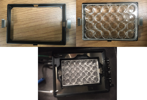
2) To use smaller vessels, first put the primary adaptor into the well plate insert:
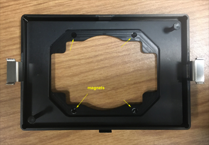
3) The secondary adaptors allow a choice of several different smaller specimen vessels. Some pretty strong magnets hold everything in place.
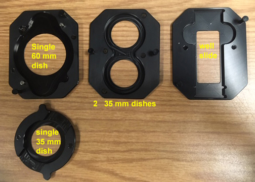
There are lids for each type of container:
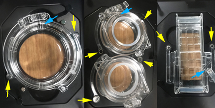
The yellow arrows point to magnets that secure the lid to the adaptor plates. The blue arrows point to ports for use of the sensor probe, or for tubing to add reagents to your specimens while imaging.
The incubator lid
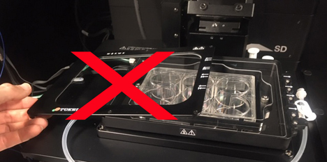
This lid has its own heating element and is balanced so that you can slide it all the way to the edge of the bath chamber and it will stay on:
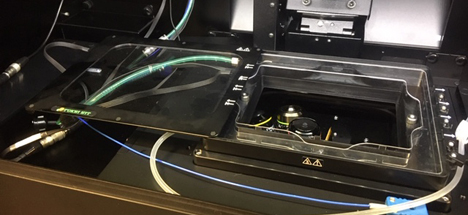
However, if you only slide it halfway, it will fall off, so don’t do that!
Perfusion Ports
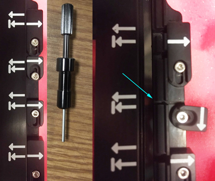
There are 4 perfusion ports on one side of the incubator that can be used for sensor probe access and/or delivery of reagents into your specimen vessels. The black screwdriver (stored in the top left drawer of the computer desk) allows you to open the port covers.
The more detailed instructions for incubator use:
1) Turn on the FV30000 system.
2) Install the lens heater (optional)
An objective that is close to the specimen can act as a heat sink and lower the temperature, which can interfere with results. Therefore use of this device is recommended if you are doing extended imaging with any of the oil immersion objectives (30x, 40x, or 60x). You may or may not wish to use it with the 20x, depending on the requirements of your experiment. It is not needed for use with the 2x or 10x.
There is the option to remove neighboring objectives to make this install easier, but you must ask the Core Manager to do this. Also, this is the time to put oil on the objective (if needed). The objectives will not be accessible for oiling once the incubator is installed.
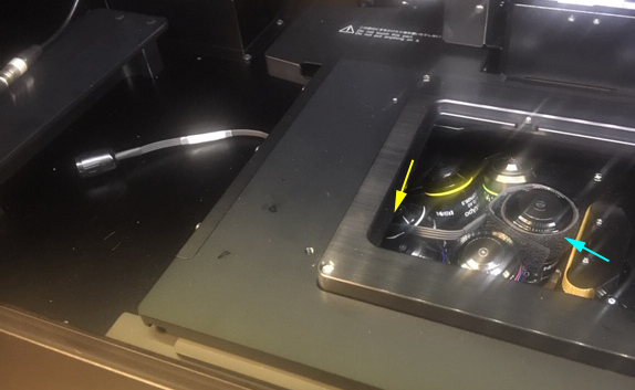
The heater portion is secured around the objective with Velcro (cyan arrow). Make sure that it fits snugly. The wire should be passed through the bottom opening in the stage to the left side (yellow arrow). You will attach it to the stage wires in step 7.
3) Place the chamber on microscope
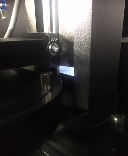
Check the height of the condenser. On the right side there is a piece of blue tape that marks the lowest safe position of the condenser (where it will not collide with the incubator lid). If it is below that, raise it at least to the level of the tape with the large knobs at the top. Always tilt down the condenser slowly and carefully when the incubator is installed. The incubator lid is glass, you can beak it if you are not careful, and it will cost your lab $2000 to replace!
Tilt the condenser back on the FV3000. Put the incubator chamber into the opening on the stage, with the perfusions port side on the right. Press down on it carefully to insure that it is properly seated. Hang the bundled wires on the silver hook at the back left of the stage enclosure.
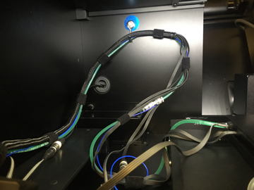
The Blue wire for the sensor probe and the water inlet tube should be placed on top of the stage in front of the incubator.
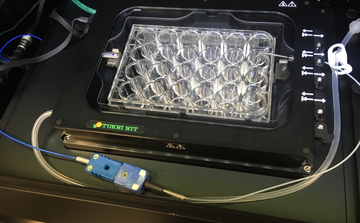
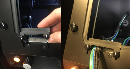
Move the stage around (within the range you anticipate using for your imaging session) to check for any issues with the wires getting caught on the stage or pulled too tight. Move the bundle up or down on the hook if needed. Then secure the wire bundles at the port where it enters the stage enclosure.
4) Insert sample holder and sample
Assemble the necessary parts to hold your specimen container. For a well plate, just insert it firmly into the well plate adaptor. If you wish to use the feedback probe (see step 5) leave the plate lid off. For smaller containers, assemble the necessary adaptors, and insert your container. If you are going to use the feedback probe, don’t put on the lid at this step. Any dummy wells you plan to use should be on the right side (where the perfusion ports are). Otherwise attach the lids so that the magnets collect.
Remove the lid and the water bath insert from the incubator and set them carefully to the side of the stage. Put the specimen container assembly into the incubator. Press down carefully to make sure it is all the way to the bottom.
5) Connect sample feedback probe (optional)
This probe gives you a direct measurement of the temperature in your vessel via a dummy well filled with water. It is recommended, but not required to run the incubator.
If you are using a well plate, reserve an empty well of the right side of the plate for the probe. Open one of the perfusion ports and run the probe wire through it. Fill the dummy well with de-ionized water (from the BBIC supply only). Make sure that the probe tip is immersed.
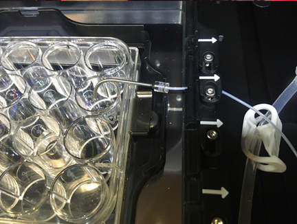
If you using a smaller vessel (dish or well slide), you will need to insert the sensor probe through the opening in the lid.
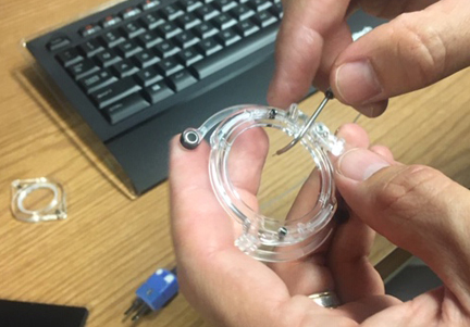
Run the probe wire through an open port after you place the probe tip and attach the lid. Plug the probe into the blue outlet in the stage wire bundle.
If you plan to introduce compounds into your specimen wells, you will follow these steps in placing your tubing.
Check the ports not in use to insure that they are closed, so that the chamber atmosphere does not leak out through them. There are two arrows on the chamber lid, the closed arrow (short arrow pointing to a bar), and an open arrow (longer arrow). The open/closed status of the port is indicated by which one of these the arrow on the port cover aligns with.
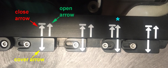
In this picture the 3rd port is open (*), and the other 3 are closed.
6) Fill water bath and install water bath cover
The water should be filled only with distilled (NOT Milli-Q or RO) water. The Core keeps a supply on hand. Use the syringe to fill the bath. There will be surface tension effects, so dispense drops at multiple places. Do not fill above the silver gas inlet at the top left corner.
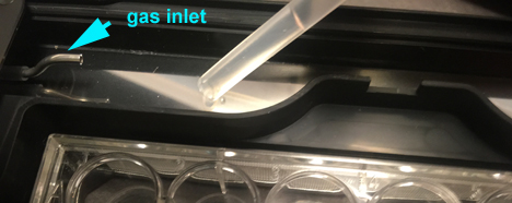
Replace the water bath insert. Once the water bath is filled, do NOT take the incubator off the stage. If you find that you have to remove it, you must remove the water first to avoid spills onto the objective turret.
7) Install chamber lid, and connect lens heater
Latch the lid shut. The latch is located on the corner under the perfusion ports.
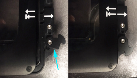
If you are using the lens heater, attach it to its plug.
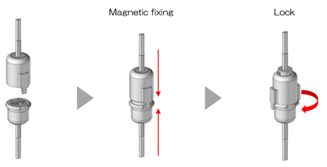
8) Open gas cylinders (optional)
If you are working with cells in culture, you will most likely need CO2. O2 levels can be controlled if needed by displacement with N2, such as reducing the level to 13% (to better simulate standard physiological conditions) or to 0.1% (for hypoxic conditions).
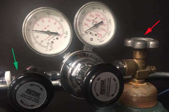
Open the cylinder valve, then the valve on the left. DO NOT move the middle valve; it is set so that the gas will flow at 16 psi.
9) Power on BOTH control boxes
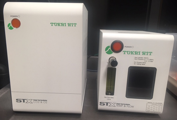
These are kept on the big grey cart. Even if you are not using gas, turn the gas mixer (left) box on. Don’t worry about adjusting the ball valve on the Temp & Flow box (right); it has been bypassed. Just use the touch screen.
10) Adjust gas and temperature settings and wait for equilibration before imaging
For most cell culture experiments, these default temperature settings are the ones you will use. If you are using the feedback probe, touch the screen to turn it on. SV is set value (what you want) and PV is process value (the current reading).
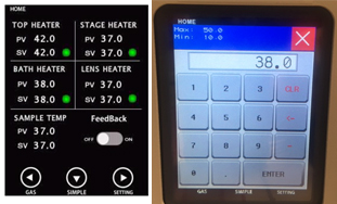
If you want to change a temperature setting, touch a green dot, and you will see the panel on the right. Hit “CLR”, type in the new temperature (which must be in the range specified in the top left corner), and then press “ENTER”.
The choice of settings for the lens heater will depend on the working distance of the objective and the type of vessel you use:
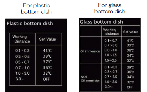
If you are not using the lens heater, you will see the yellow triangle icon next to the PV value on the screen.
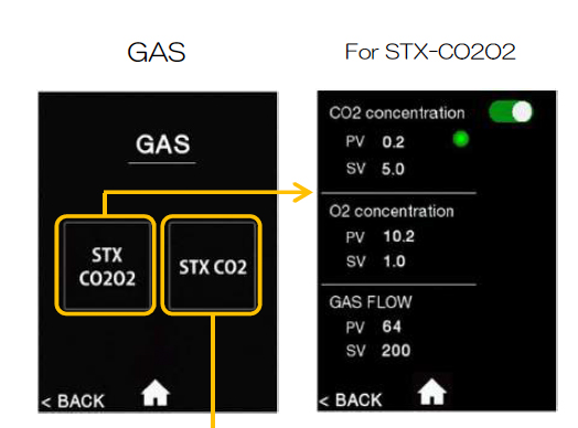
To set gas levels touch “gas” on the bottom left of the screen.
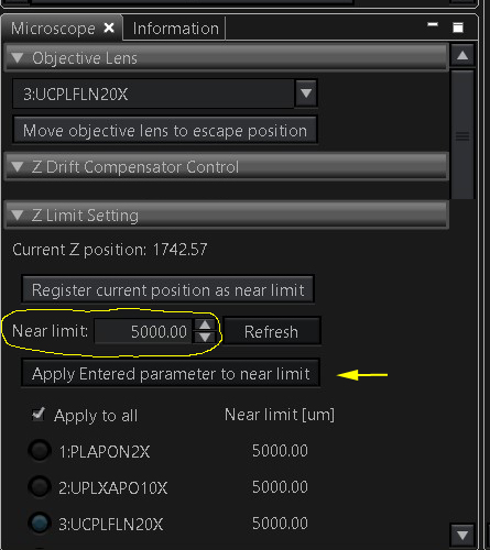
11) Adjustments to Z-limits
The stage will raise your specimens higher, so the Z-limits must be changed to allow the objectives to reach the specimen. The setting is in the “Microscope” tab under “Z Limit Setting”. For slides this setting is usually 1800-2000. If you are using a glass bottom vessel, reset this to 3200 (type in the new number and click the “Apply” button below it. If you are using a plastic dish (which will have a thicker bottom), use 5000 as your limit. It is rare to need a higher value, but you can go to a maximum of 10,000. This setting should be returned to 1800-2000 after your imaging session.
12) To shut down
Turn off the control boxes.
Close the gas cylinders (if you used them).
Disconnect the lens heater and the sample probe (if you used them).
Remover the chamber lid and use the syringe to remove the water from the chamber bath.
Remove the sample holder/sample from the chamber.
Replace the lid on the chamber, remove the chamber from the stage and set it on the cart.
Disassemble the sample holder inserts and put them back in their storage boxes.
Remove the sample probe from the specimen holder (if you used it).
Remove the lens heater (if you used it) and place it in its box on the cart.
Rinse chamber bath and tip of sample probe with 95% ethanol (kept in a spray bottle on the bottom self of the cart). You need to spray any surfaces that came into contact with water. There is an aqua bowl on the bottom shelf of the cart for spraying and pouring off the ethanol.
Set the chamber into its box on the top of the cart to dry. Put the sample probe back in its box.
(Under construction, check back soon)
