Leica Z stacks
Scan modes with a “z” dimension allow the user to collect images in multiple optical planes. The use of a pinhole in collecting the light from the specimen prevents the out-of-focus light from obscuring the in-focus image. Z-stacks can be merged to create a detailed 3 dimensional representation of the sample.
If you select the “xyz” mode without defining any start/end points for the z-axis, you can still collect data, but it will just be in the current optical plane (essentially an “xy” scan).
The Z-stack panel allows you to set the Z-parameters:

The first thing you should check is whether the drop down is set to “z-Wide”. Our system is not equipped to use the “z-Galvo” mode, so select “z-Wide”.
The buttons you will use most frequently set the start and end of the z-stack, and are located on the top left of the panel:

To set up a z-stack, find a region of interest via the eyepieces and bring it into focus. Click the “Live” button to scan, then adjust the gain and offset.

Next you will need to turn the focus knob (You can use either the USB control panel or the focus knobs on the STP6000 box) in one direction (it doesn’t matter which) until the useful signal from your specimen starts to disappear. Turn a little further and click “Begin” to set your start point.

Now turn the knob in the opposite direction until you have moved past your sample from the other direction. Click End. Two new windows (marked with yellow *), with values for the beginning and ending z-coordinates, will appear to the right.

Be aware that the optimal exposure levels you set at the beginning may turn out to be not so optimal as you focus up and down through the sample, so adjust them as needed. If you are scanning with more than one detection window you will need to check the levels for each one, at different points of the z-stack. The “Move to Begin” “Move to Center” and “Move to End” buttons are very useful here. You should check these positions to see whether your stack settings will collect all the data from these channels. For example, if you set your start/end points based on a nuclear dye imaged in the first detection window, but you also are detecting a membrane marker with a different fluor, basing your stack limits on the nuclear stain might cut out some of the membrane stain. Always check every channel; you can re-click on a set button to add more z layers if needed. It’s also a good idea to err on the side of extra stacks. Anything that does not have much useful signal can always be edited out later, but if you set the start/end points too short you will have to redo the scan.
Once you have set your begin/end points, the panel will tell you many optical sections there are, and their thickness:

When “System Optimized” is on, the software will select a “recommended” optical section thickness, based on the objective and laser line in use. Clicking the “+” bar shows you the formula and give you to option to apply if it isn’t already active.

You are free to disregard the recommended z-step size and type in any compatible number. This will change the total number of z steps. You also have the option to specify the number of z steps.
After you do your scan, you can click the “Maximum Projection” button to merge the z stacks:

Your start/end points can be cleared by clicking the trash can icon, or you can turn the focus knobs and click the set buttons to set new start/end points.
Editing z-stacks
The “Crop” function in the “Edit” portion of the “Process Tools” allow you to copy and isolate a subset of the xy frames and create a new file.

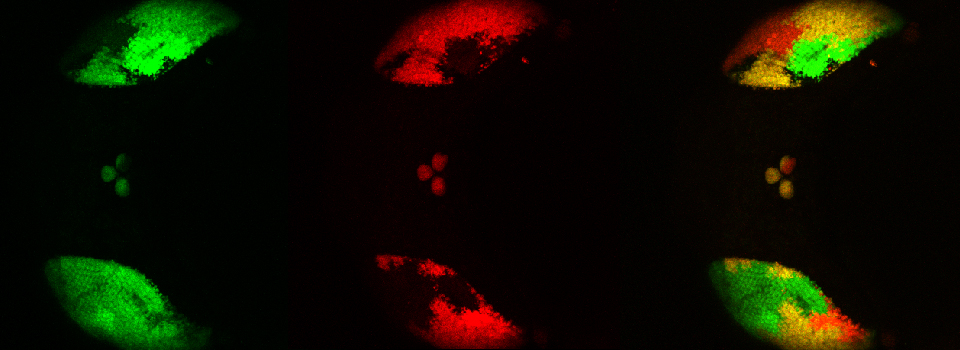
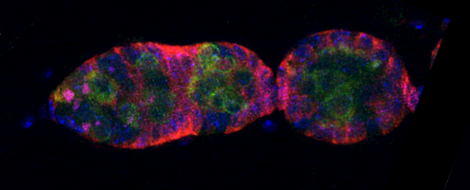
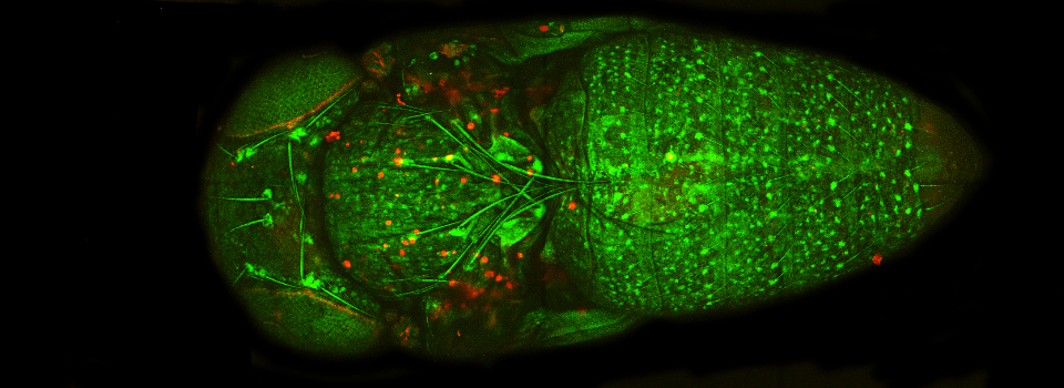
In the example above, an xyz scan of a GFP-expressing mushroom body in an adult Drosophila brain, there are 291 xy frames in the stack. When the frame are merged (with Maximum Projection) the image looks like this:

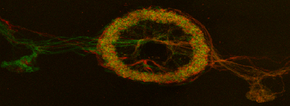
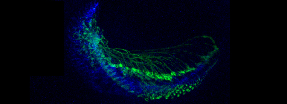
If you wanted to produce a picture of just part of the structure, such as only the calyx, without the rest of the mushroom bodies obstructing the view, you can edit the Z-stack to include just those frames showing the calyx structures. Use the Z-slider bar on the right side of the image windows to find the portions of the Z-stack that have the region of interest. Note the stack # (cyan arrow in the picture below). In the example, frame 291 would be one end of the selected frames.

In this example frame 133 is selected as the other endpoint:

To crop the stack, select the “Process” tab at the top of the panel, The “Process Tools” tab on the upper left, then Edit> Crop. Use the panel at the bottom center to put in the desired stack numbers, then click “Apply”.

The new file will appear at the bottom of the open experiment file stack, with”Crop” included in the name (Highlighted in red). Note that the original Z-stack (cyan arrow) is still there, unchanged.

The stacks in this new file will be renumbered, starting at 1, regardless of which stacks were selected from the original. In this example, the number of frames has been reduced to 159.

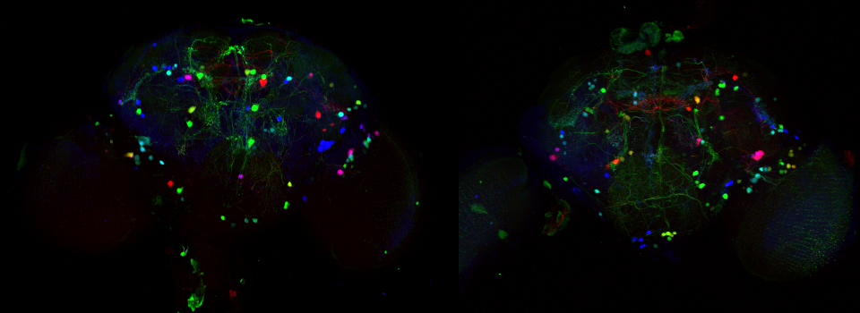
The cropped stack can be merged with “Max Project”, just like the original. The picture below shows a merge of the original stack next to a merge of the cropped stack:

The new Crop file can be treated in any manner that the original can, including being further cropped.

In the example above, 3 frames from the cropped stack were selected to generate a new stack. It is named Crop001_Crop001 in the experiment file.
